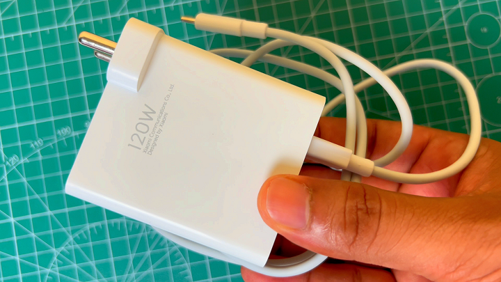
A while back, a friend came over to my place for a party. Unfortunately, his phone battery died, so he asked me for a charger. I handed him my 120-watt fast charger, but he hesitated and said, “My phone only supports 20 watts, won’t this 120-watt charger damage it?”
That’s a pretty common concern among non-techies, so I reassured him, explaining that he didn’t need to worry. The charger would only deliver 20 watts to his phone, not more.
He was curious, though, and asked, “How does a 120-watt charger safely charge my 20-watt phone without causing any damage?” I figured this is a question a lot of people might have, so I decided to write a article explaining it in detail.
In this article, I’ll dive into how USB Power Delivery works, how smartphones negotiate the right amount of power from a charger, and to make things more interesting, I’ll show you how you can decode the power outputs of a PD charger using a custom-designed module I built.
I’ll walk you through the schematic of this USB Power Delivery decoder, explain the features and specifications of the CH224K IC, which is the core component of this module, and demonstrate how it works in real-time.
Working of USB Power Delivery.
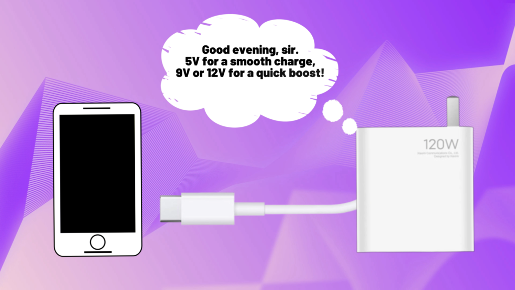
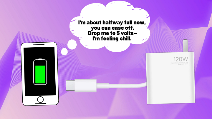
As soon as you plug your phone into the charger using a USB Type-C cable, a handshake begins between the charger and the phone. This isn’t a typical conversation, but an exchange of information about power requirements and capabilities.
This initial communication happens through a data line in the USB cable. The charger sends a message to the smartphone detailing the power profiles it can provide, such as 5V, 9V, 12V, or even 20V, along with the current available for each voltage.
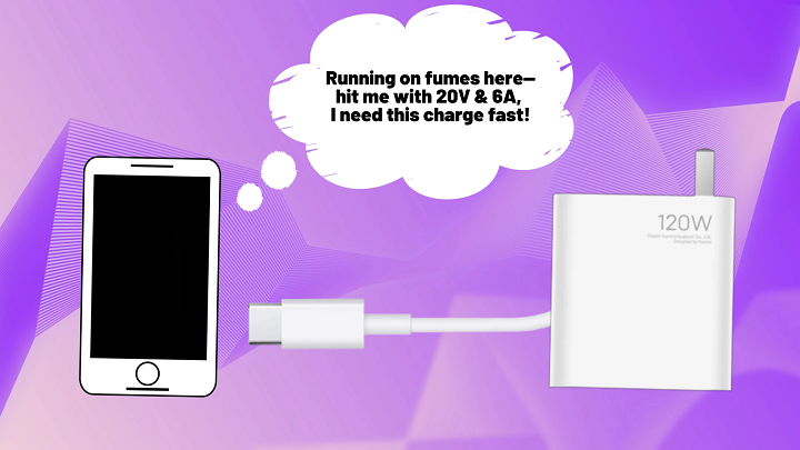
In response, the phone requests the power it needs based on its battery level, supported charging speed, and the charger’s capabilities. For example, if it’s a fast-charging phone, it might request 9V or 12V, while for standard charging, it may stick with 5V. The charger then adjusts its output voltage and current to match the phone’s request.
This dynamic negotiation ensures the charger delivers exactly the right amount of power, preventing overloading or damaging the phone or its battery. The USB Power Delivery (PD) system also ensures efficient and controlled charging, which helps reduce heat generation and prolong battery life.
As the battery nears full charge, the phone decreases its power draw, transitioning to trickle charging to avoid overcharging and protect the battery. This smooth transition between charging stages is part of what makes the PD protocol so reliable.
However, older phones that cannot communicate with PD chargers will default to the standard 5V output, as they lack the ability to negotiate higher voltages.
Now, what if we wanted to use these PD chargers to power other devices, like appliances that require up to 20V? The issue is, when the charger doesn’t detect proper communication with the connected device, it defaults to 5V, since that’s the standard.
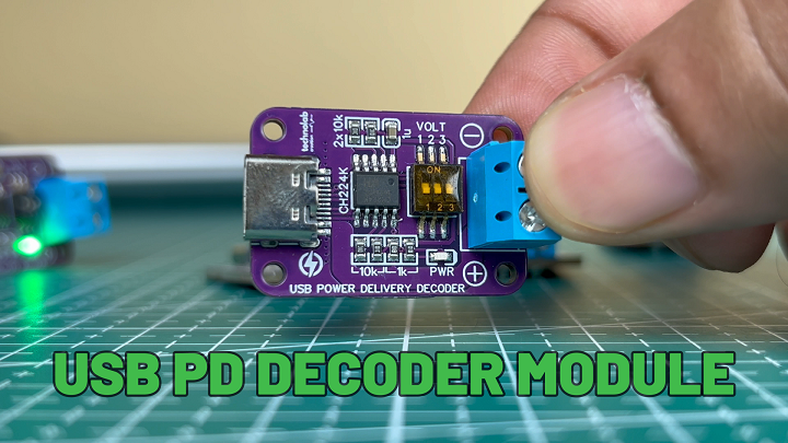
To solve this, I’ve designed a module that can “talk” to the charger on behalf of the device. This module communicates with the charger and allows you to select the desired output voltage, unlocking the full potential of the charger.
Schematic of PD Decoder Module.
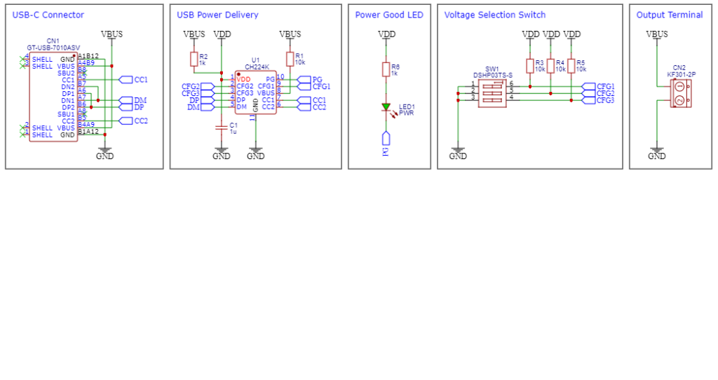
This schematic begins with the USB-C connector, which links to the USB Power Delivery (PD) source.
Pins A4, A9, B4, and B9 carry the voltage from the USB PD source.
CC1 and CC2 (pins A5 and B5) are the Configuration Channel pins, which handle the negotiation of power levels between the device and the USB PD source.
DP and DM are the data pins, typically used for USB communication, but they don’t play a role in basic power negotiation in this case.
The key component in this module is the CH224K IC, which is responsible for negotiating the power delivery from the USB-C source. It communicates through the CC1 and CC2 pins to request specific power levels.
VDD1, CFG1, CFG2, and CFG3 are configuration pins used to select the desired voltage from the USB PD source. Depending on the values applied to these pins, the circuit can request different voltage levels.
PG (Power Good) is an indicator pin that signals when the correct voltage has been negotiated, meaning the USB source is ready to provide power.
Resistors (R1, R2, R3, R4, R5, R6) are used to help with the power negotiation process by setting up the necessary pull-up or pull-down configurations on the lines.
Capacitor C1 acts as a decoupling capacitor to stabilize the voltage supply and filter out noise from the power source.
A voltage selection switch is used to choose the desired output voltage.
The LED serves as a Power Good indicator. It lights up when the correct power has been negotiated and is ready for use.
Finally, the output is provided through the CN2 screw terminal connector, from which you can easily access the negotiated voltage to power any external load.
PCB Design.
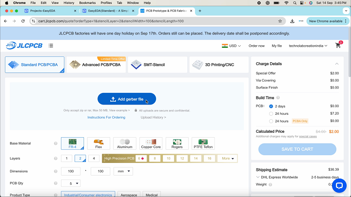
After finalizing the schematic, I designed the custom PCB and placed an order for it with JLCPCB for manufacturing. JLCPCB is a leading PCB manufacturer in China, known for providing high-quality, reliable PCBs at an affordable price.
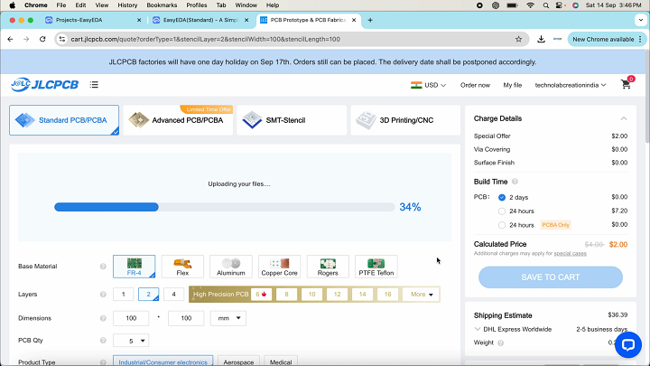
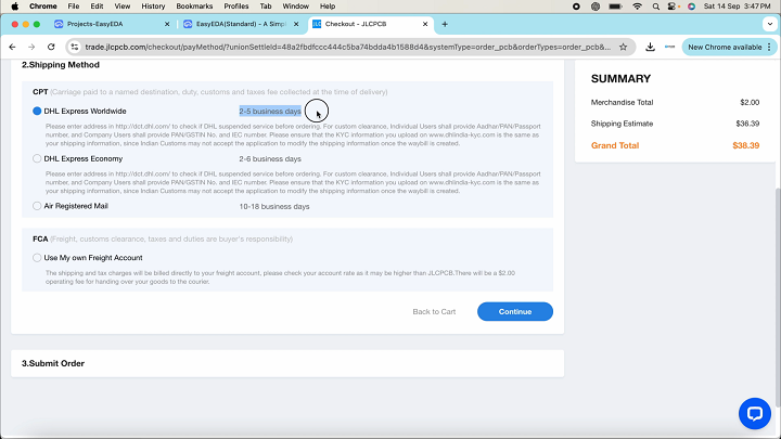
Ordering a PCB from JLCPCB is straightforward. Simply upload your Gerber file.
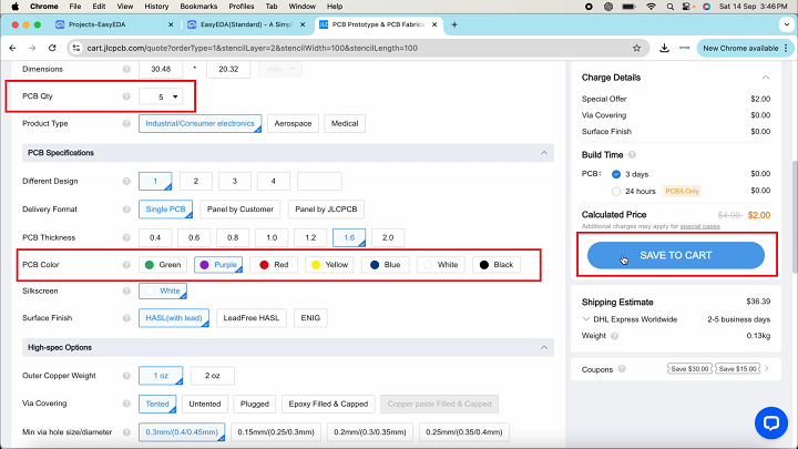
Select the quantity, choose the solder mask color, and then click “Save to Cart” to complete your order.
If you opt for the fastest shipping method, your PCB will be delivered to your location within a week.
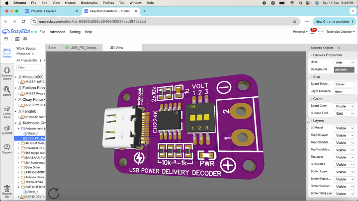
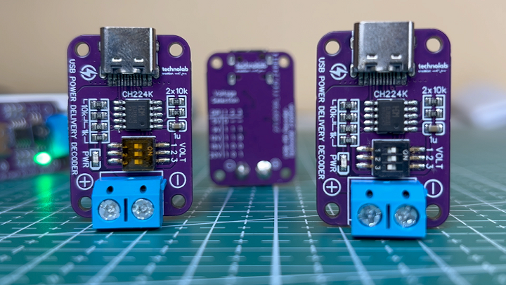
In my case, after just five days, I received my PCBs in excellent packaging. As always, the quality was top-notch, and the PCBs looked very professional. The purple solder mask I chose really made the design stand out—it looks fantastic!
In addition to PCB manufacturing, JLCPCB also offers PCB assembly services, 3D printing services, and now even multicolor silkscreen options for PCBs. If you have any upcoming PCB projects, I highly recommend trying JLCPCB.
PD Decoder Module Testing.
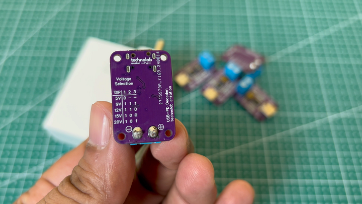
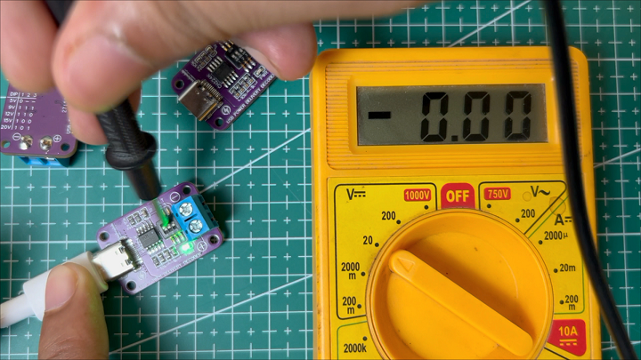
Let’s test the PD Decoder module. If you look at the back of the module, you’ll find the switch configuration for different voltage selection options like 5V, 9V, 12V, 15V, and 20V. You can choose any voltage from these options.
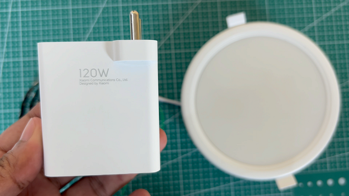
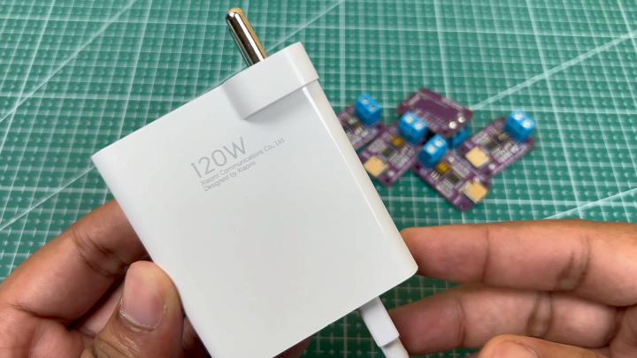
I have my 120W fast charger here, and if you check its output, it provides 5V, 9V, 11V, 17V, and a maximum of 20V.
Now, let’s connect the PD Decoder module to the charger using a Type-C cable.
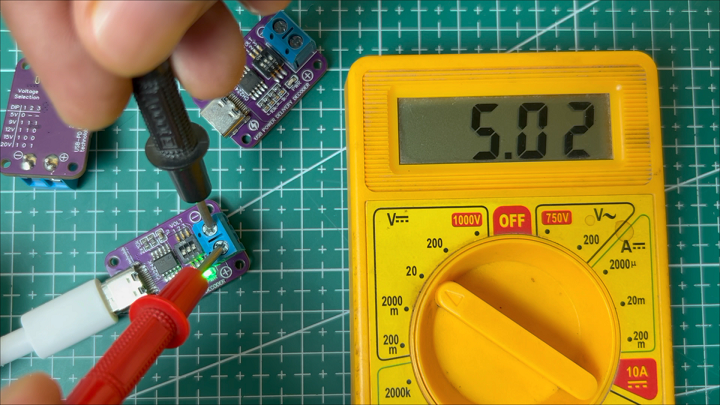
By default, the module will give a 5V output when the first button is OFF. Let’s check the voltage… As you can see, the output voltage is 5V.
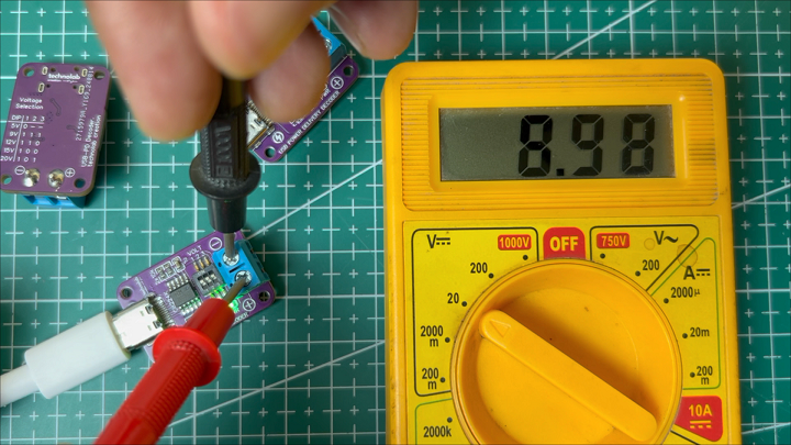
Now, let’s test another voltage. If we turn all the buttons ON, the module should output 9V. So, let’s go ahead and turn them on.
As you can see, the output is close to 9V. This means the charger is now delivering 9V instead of 5V.
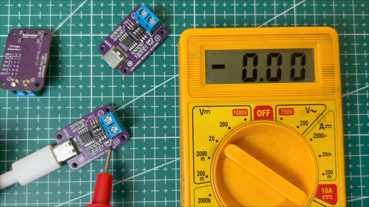
Next, if we turn ON the first and second buttons and turn OFF the third one, it should set the voltage to 12V. Let’s check that.
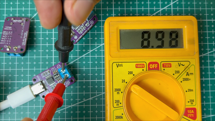
As you can see, the LED isn’t lighting up, which means the charger isn’t able to deliver 12V. As we saw earlier, this charger outputs 11V, not 12V. So, the module can’t get the desired 12V. If we check the output, it’s still at the previous 9V.
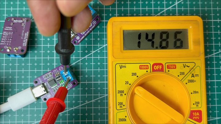
Now, let’s change the switch configuration again. If we turn OFF the second and third buttons, leaving only the first button ON, the voltage selection will be 15V. Let’s check the output… and there we go — it’s almost 15V, close enough!
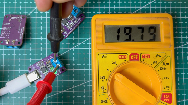
Lastly, if we turn ON the first and third buttons and turn OFF the second button, it should give us a 20V output. Let’s test it.
As you can see, the output is close to 20V, meaning the PD charger is now delivering 20V.
So, in this way, you can select different output voltages depending on your needs. This PD Decoder module has a screw terminal connector for the output, so you can use it to power appliances rated for 9V, 15V, or 20V, all with your smartphone’s fast charger.
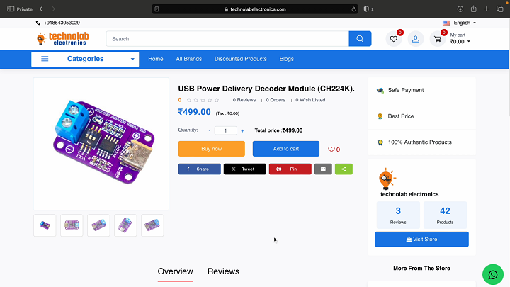
If you’re interested in this module, you can purchase it from my website, technolab electronics.